

SUBSCRIBE TO THE NEWSLETTER
Receive updates about our latest products, application reports and white papers - right in your e-mail inbox!
Starting situation
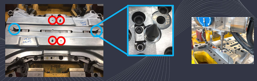
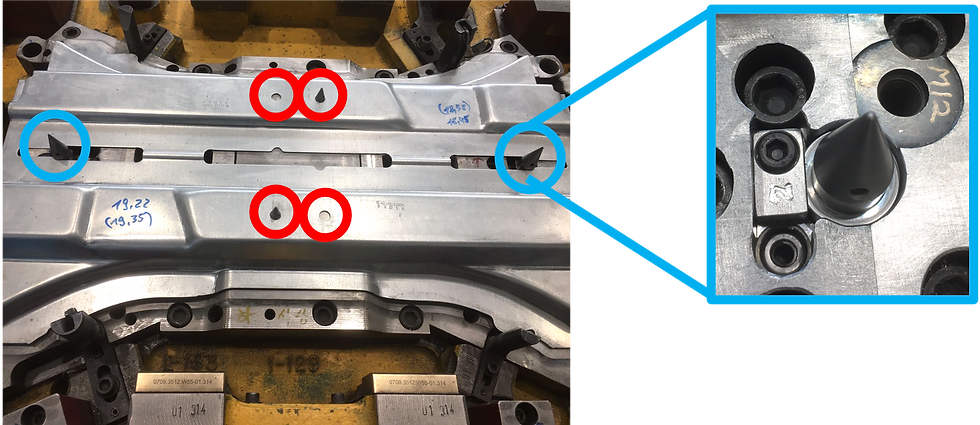
Due to a technical change in the sheet metal part to be produced, two through-holes in the sheet metal part are omitted. As the component must be repeatably positioned accurately in every forming operation of the tool set, various so-called guides are used. These ensure that the component is guided into the same position each time it is inserted into the tool (whether manually or mechanically in the press line). Some guides are usually attached to the outer edge of the tool and ensure that the sheet metal part is pre-positioned when it is inserted. Fine guides then ensure the exact position of the sheet metal part in the inserted state. Existing holes in the sheet metal are often used for this. The component is centered in the hole by a conical guide. In this case, the holes previously used for centering were omitted. As the component had to be positioned even without the holes, a new solution was found to center the sheet metal part on existing contours. A total of four new fine guides had to be inserted in two operations of the tool. The necessary work involved milling the cylindrical seat and the necessary fixing/screwing of the guides in the lower part as well as the clearance for the new guides in the upper part so that there is no collision in the tool.
Procedure
First of all the sheet metal part was inserted into the forming operation using the previously used guides and digitized. From the scan, we were able to determine the exact position for the fit of the new fine guide so that the sheet metal position is identical to the original. This eliminated any discrepancies between the design data and the tool. As the previously determined position of the new guide is between two tool inserts with different material hardness, it was necessary to produce the cylindrical cut-out in two steps, as different process parameters are required due to the change in material. First, the hardened insert was dismantled, and the machining was carried out in the comparatively soft tool steel. Suitable milling tools for machining hardened steel (> 60HRC) were then set up and machining was completed using suitable tools and parameters. In addition, the necessary milling was carried out in the upper part of the tool. Finally, the function of the new guides was tested by installing the old and new guides at the same time. The sheet metal part was inserted and checked to ensure that both the old and the new guides were in contact with the sheet metal part, thus ensuring correct positioning. Finally, the old guides were dismantled and some sheet metal parts were produced using the newly installed guides. These were checked by customers for quality and dimensional accuracy and found to be free of defects. By removing the hole punches, which punched the previously used holes in the sheet metal part, the customer modification was successfully completed.
Advantages
We could avoid expensive and time-consuming transportation of the tool, which weighed several tons, with our approach. In addition, the customer change could be implemented in the shortest possible time ready for the next scheduled production. By using our measuring technology, the correct position of the fine guide could be determined straight away and manual corrections were no longer necessary.
%20Nr%20002.jpg)
%20Nr%20001.jpg)
%20Nr%20004.jpg)
%20Nr%20003.jpg)